KMA ULTRAVENT® T — The tandem of
heat exchanger and electrostatic precipitator
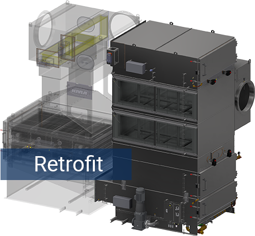
Heat exchanger and electrostatic precipitator in tandem for hot, high-temperature exhaust air – both components can be installed individually and retrofitted to each other.
Heat Recovery and Exhaust Air Filtration in One System
The ULTRAVENT® T combines a heat exchanger and an electrostatic precipitator as a tandem into one integrated solution for processes where hot, humid exhaust air contains oily, pasty aerosols, smoke, or dust. In these high-temperature processes, the system ensures reliable exhaust air filtration with an electrostatic precipitator (ESP), sustainably lowers energy costs, and specifically recovers valuable process heat. Thanks to the tandem design, a later ESP retrofit remains possible.

High humidity
High
temperature

Oily, greasy,
pasty aerosols

Smoke
or dust
Our customers’ business cases prove it:
Two Components Combine Energy Recovery and Emission Reduction
Hot exhaust air heavily laden with oily, greasy, or pasty particles also carries valuable waste heat from the high-temperature process. The ULTRAVENT® T combines powerful heat exchangers with highly effective electrostatic precipitators. This concept enables particularly economical use of waste heat and reliable separation of emissions.
The KMA ULTRAVENT® Tandem
Capacities & configurations
Exhaust air filter capacity
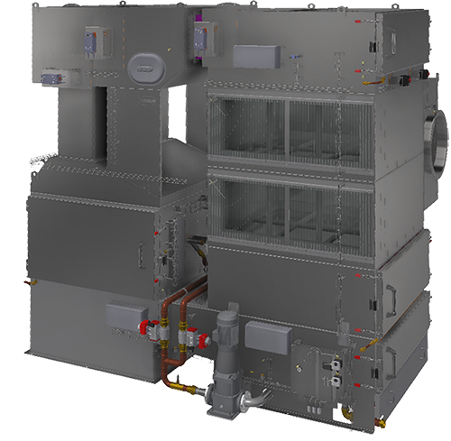
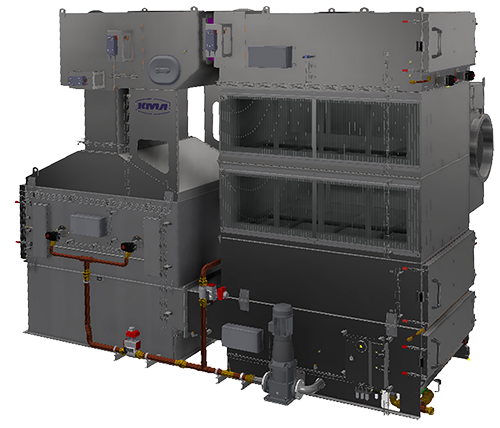
The ULTRAVENT® Tandem is available for exhaust air flow rates of 15,000 m³/h, 20,000 m³/h, and 30,000 m³/h. Combining several filter systems provides solutions for higher exhaust air flow rates. The width of the filter system depends on the exhaust air filter capacity.
The filter housing is made of pickled stainless steel. The filter cells and heat exchanger can be installed in either aluminium or stainless steel versions.
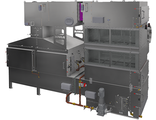
Component: heat exchanger
The heat exchanger of the ULTRAVENT® T uses the thermal energy contained in the exhaust air and makes it available to the process again in a targeted way. This reduces the need for conventional heating energy and noticeably lowers the total energy consumption of the production process, e.g. the stenter frame.
Mechanical lint filters protect the heat exchangers before the exhaust air even enters, ensuring reliable and efficient operation.
The tandem design provides flexibility, allowing both components to be installed individually and retrofitted to each other.
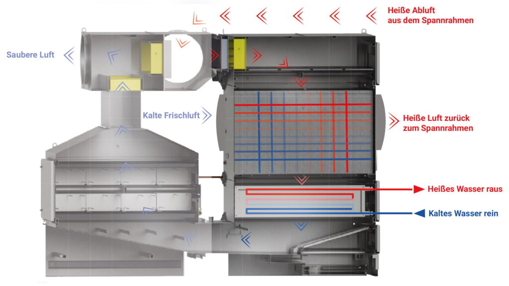
Different ways of using heat
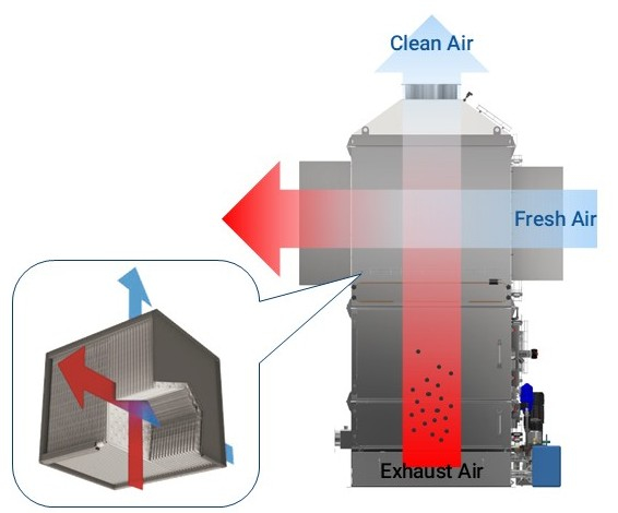
Air-to-air heat recovery
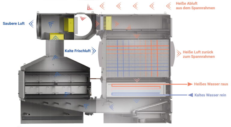
The ULTRAVENT® T enables the integration of powerful air-to-air heat exchangers for the effective recovery of process energy from the exhaust air to heat the fresh air.
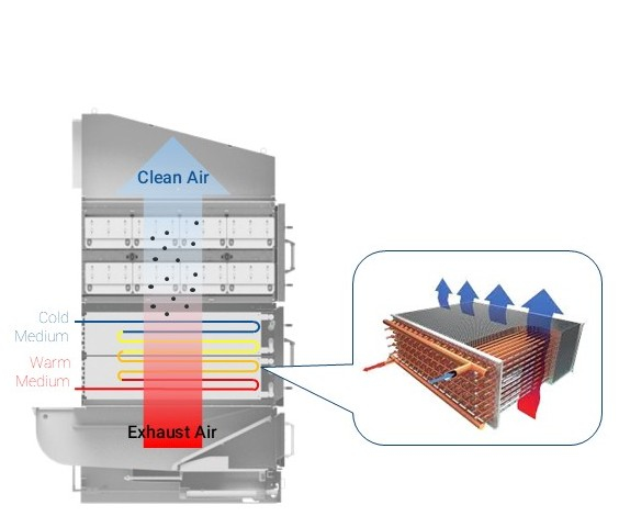
Air-to-water heat recovery
The ULTRAVENT® T enables the integration of powerful heat exchangers for the effective recovery of process energy from the exhaust air as well as for cooling and condensation during exhaust air filtration. Depending on the application, the heat exchangers can be operated with water or glycol.
Component: electrostatic precipitator
The electrostatic precipitator of the ULTRAVENT® T efficiently cleans the exhaust air of smoke, dust, and oily, greasy, and pasty particles. Separation takes place electrostatically with low energy consumption. The particles are charged and reliably collected on the collector plates.
The vertical airflow protects the electrostatic precipitator from dripping substances from the heat exchanger and, together with the integrated cleaning system, supports reliable and efficient operation.
The tandem design provides flexibility, allowing both components to be installed individually and retrofitted to each other.
How electrostatic charging works
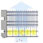
Ionisation
The high voltage at the ionisation profiles creates an electric field. Particles passing through are charged here.
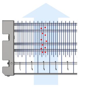
Separation
Earthed separator plates attract the passing particles and retain them with minimal air resistance.
Automatic integrated cleaning
Exhaust air from high-temperature processes, such as at the stenter frame, largely consists of fibre dust and oily aerosols. Heat exchangers in particular are prone to fouling and wear. Manual cleaning is time-consuming and dirty.
With automatic cleaning in place (Cleaning in Place “CIP”)
- the ULTRAVENT® T relieves the burden on maintenance staff,
- reduces cleaning effort to a minimum, and
- protects the technology from wear.
Similar to a household dishwasher, the integrated cleaning system offers a choice of different programmes. The filter cells and heat exchanger are cleaned automatically within the filter system, minimising unwanted interruption times in the production plant. The cleaning system, developed over many years, achieves unique effectiveness while conserving resources.
You are currently viewing a placeholder content from YouTube. To access the actual content, click the button below. Please note that doing so will share data with third-party providers.
More InformationCombined heat recovery for maximum energy savings
The ULTRAVENT® T specifically uses the process heat contained in the stenter exhaust air to return heated supply air and to provide hot water for downstream processes. This sustainably reduces energy consumption, operating costs, and CO₂ emissions.
- Heat recovery from process exhaust air: low operating costs, less CO₂
Thanks to the flexible configuration of energy use from air-to-air, air-to-water, or combined heat recovery, the ULTRAVENT® T offers the greatest possible energy efficiency. This reduces energy consumption and operating costs while also lowering CO₂ emissions and, in the long term, CO₂-related costs.
- Automated cleaning system: constant performance, lowers energy consumption
Conventional heat recovery systems are prone to fouling and wear of the heat exchangers due to fibre dust and oily aerosols. The integrated cleaning system in the ULTRAVENT T ensures consistently high heat transfer performance of the heat recovery system through regular cleaning cycles. This significantly reduces the energy consumption of the stenter frames. In addition, the CIP cleans both the electrostatic plate precipitator and other (optional) filter components, ensuring consistently high performance and a long service life for the filter system.
- Demand-based waste heat utilisation: high potential savings, lowers operating costs
By combining the use of the air-to-air and air-to-water heat exchangers, not only can the heated supply air be returned to the stenter frame or used for heating, but hot water can also be provided for downstream dyeing or washing processes. This unique solution offers high potential savings through maximum use of the available waste heat.
FAQ — Questions about the ULTRAVENT® T
Why tandem — what does the combination offer over two separate systems?
Because the two stages in tandem achieve more than each could on its own. The heat exchanger sits at the front and extracts energy from the hot exhaust air — in doing so, it also cools it down, which is exactly what the electrostatic precipitator behind it needs in order to reliably separate oil and grease. Conversely, a shared cleaning system ensures that the heat exchanger stays permanently clean and therefore efficient. Two separate systems can’t support each other in this way: they take up two footprints, require two maintenance regimes, and lose pressure and heat at every interface. For an initial assessment, a photo of the situation above the stenter frame is often enough for us.
Can the ULTRAVENT® T be retrofitted for heat recovery?
Yes — retrofitting to an already-running stenter frame is the standard case, not the exception. The ULTRAVENT® T is installed as a complete unit on or next to the stenter frame and connected to the existing exhaust ducting; the frame’s own process technology is not affected. Because the unit has a modular design, you can also start with pure heat recovery and add electrostatic separation later — the interface for this is built in from the start, so the expansion doesn’t mean a new system. For an initial assessment, we need the exhaust air flow rate, exhaust air temperature, and the overall height above the frame; if these figures aren’t available, we’ll determine them together on site.
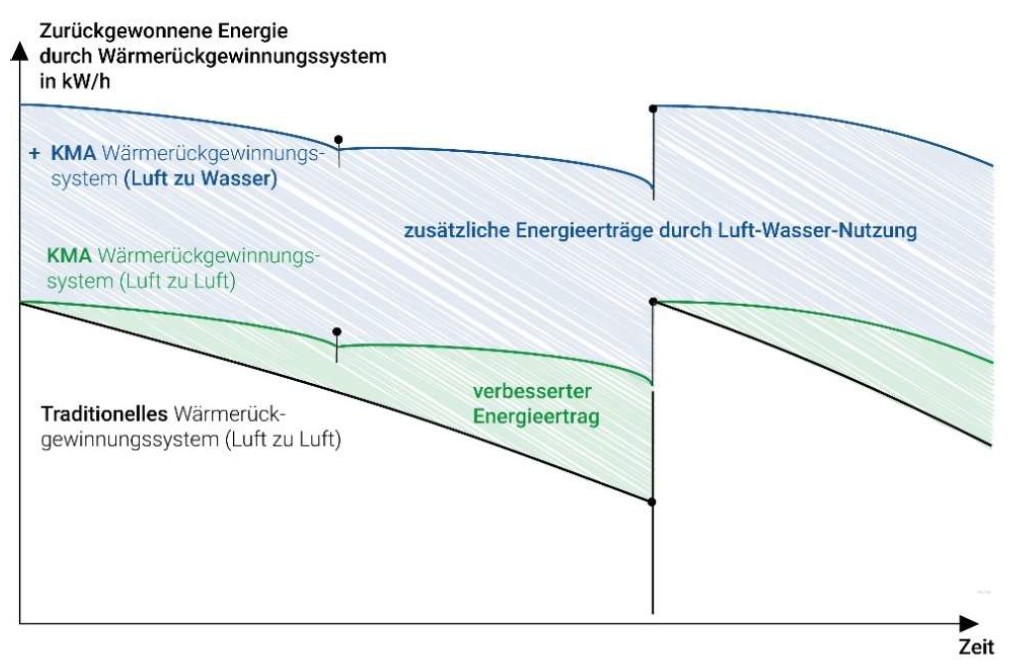
Why does heat output decline over time with other systems — but not with the ULTRAVENT® T?
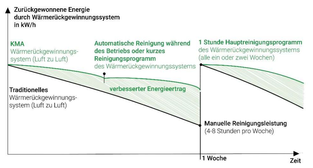
Because stenter exhaust air contains airborne fibres and oily aerosols that settle on the heat exchanger surfaces — and every deposit acts like an insulating layer between the exhaust air and the fresh air. With a system that is only cleaned by hand, the recovered output therefore starts declining from the very first day of operation and only returns to close to its initial value after the next cleaning; to stay anywhere near the design output at all, this typically requires four to eight hours of manual cleaning per week, as is standard in the industry. The ULTRAVENT® T instead keeps the surfaces continuously clear, so the output never drops significantly in the first place. What matters for your energy balance, after all, is not the figure on the day of commissioning, but the average value over the year.
How does automatic cleaning work with the ULTRAVENT® T?
The integrated cleaning in place system (CIP) cleans filter cells and heat exchanger directly within the system, removing airborne fibres as well as oil and grease deposits; the process is comparable to a household dishwasher, with several selectable programmes. This relieves the burden on your maintenance staff and keeps production downtime short, since the programmes can be scheduled within existing breaks. Above all, the regular cycles ensure consistently high heat transfer performance and a long service life for the system. How often and with which programme cleaning takes place depends on your range of fabrics.
How much time do I save compared to manual cleaning?
In the range of four to eight hours per week — that’s how much cleaning work heat recovery systems on stenter frames that have to be cleaned by hand typically require. This figure doesn’t come from our own marketing, but from the technology assessment that Inditex has published on heat recovery at stenter frames. With the ULTRAVENT® T, this work is largely eliminated: cleaning runs according to a stored programme, and your staff are not tied up by it. Over a year, that amounts to roughly 200 to 400 working hours — plus the downtime that would otherwise have to be scheduled for manual cleaning.
Air-to-air, air-to-water, or combined — which offers the most benefit?
In most cases, the combination offers the most benefit, and the reason is a limit that many operators only notice once the system is running. Air-to-air returns the heat directly to the stenter frame as hot supply air — the shortest path, but the amount is limited by what the frame can actually absorb, typically around a third of the exhaust air volume. Anything beyond that contained in the exhaust air would remain unused with a pure air-to-air solution. An air-to-water stage in the same unit taps into exactly this remainder and makes it available as hot water for dyeing, washing, pre-treatment, or hall heating — which is why the annual yield of the combined configuration is significantly higher than that of the air-only solution. Which split makes sense for you depends on whether there is a constant hot water demand in your plant; this can be clarified in a short conversation.
What savings have been documented by customers?
A published calculation example: at 20,000 m³/h exhaust air, 200 °C exhaust air temperature, and 50 g/kg moisture, the recovered output is around 585 kW; over 6,000 operating hours per year, this amounts to roughly 3.5 million kWh and — at the gas price of 4 cents per kWh used in the example — around €140,000 in energy costs per year. This avoids around 700 tonnes of CO₂ per year. These figures come from the Inditex technology catalogue, which lists heat recovery at stenter frames of this design as Best Available Technique and names KMA as a supplier. For your site, we’re happy to recalculate this using your operating hours and energy price.
How much more energy does continuous cleaning actually deliver?
The benefit lies not in a higher peak output, but in the output staying at that level. Every heat exchanger in stenter exhaust air starts at its design value — the differences emerge in the weeks that follow: without ongoing cleaning, the recovered output declines steadily and is only raised again by the next manual cleaning, so that operation permanently sits on the declining part of this curve. The ULTRAVENT® T cleans during ongoing operation, keeping the curve flat; the area between the two curves is the additional energy gained, and it adds up over every operating week of the year. This is why the meaningful metric when comparing two heat recovery systems is not the efficiency on the datasheet, but the average efficiency over a year — you should judge every offer by this standard, including ours.
Why is there a short programme and a main programme?
Because two different levels of fouling require two different responses. The short programme runs during ongoing operation or in brief production breaks and removes fresh, still-soft oil and grease deposits before they set — it keeps performance stable day to day without interrupting production. The main programme takes around an hour, runs weekly to every two weeks, and cleans intensively; it resets the system back close to its original value. Only the interplay of both produces the flat performance curve: the short programme prevents the steep decline, the main programme regularly resets the level — a single programme could only ever achieve one of the two. The rhythm that suits you depends on your range of fabrics: heavily finished fabrics require more frequent short cleaning, lighter fabrics less often.
How can we help?
WE FIND THE RIGHT CONTACT PERSON
Just let us know briefly what it’s about. Our sales team will be happy to take your enquiry and forward it to the expert for your field.


Other ULTRAVENT® products
We put our trust in KMA